| LIFE OF A GT |
|
|
 | |  | November 1, 2008 - I measured the maximum fender width of the MG at 58" front and 57.5" rear.
That's a bit approximate, and it assumes the fenders are fully rolled. Measuring a complete Miata subframe with 205-series tires came up with 61" front and 62" rear. So I don't need to narrow things as much as I'd feared, as long as I don't do anything too foolish with wheel and tire choices.
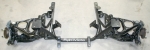
The picture is of a tubular subframe that's made for installing an LS1 in a Miata. I'm not sure if I'm going to cut down a stock Miata part or build a tubular one like this. The latter will be more work - of course - but will offer more room. Remember, I have to narrow the track by about 3".
entry 66 - tags: planning, subframe, suspension | | | 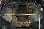 | November 28, 2008 - The nekkid engine bay.
That front subframe has mounting points that are just under 19" apart. The Miata subframe? Right about 32", as the tape measure indicates. One thing's for sure, the new subframe will free up an enormous amount of room. At the expense of a small bit of work.
entry 84 - tags: engine bay, subframe | | | 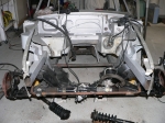 | November 28, 2008 - Here's a shot of the only MGB - that I know of - to be fitted with Miata suspension.
The car was never completed, but it's very useful info. I've shown the rear subframe installation in the past, here's a shot of what was done up front. New frame arms. I'm going to do a little more reinforcing, especially of the upper shock mounts.
This picture also shows how much more potential space there is with the new setup. Combine that with a tubular front subframe like this one and all sort of room opens up.
entry 85 - tags: engine bay, subframe | | | 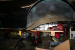 | December 6, 2008 - The engine height was set to put the oil pan at or slightly lower than the frame rails.
This is a bit of a guess, but I think it'll work nicely. I might be able to sink it down another 3/4" or so.
With this positioning, the engine ends up in almost exactly the same position relative to the wheels as the Miatas we do at Flyin' Miata. Only the front pair of cylinders are ahead of the wheels and the height looks to be the same. This means I could use an off-the-shelf subframe. Wow, could it be that easy?
The threaded holes in the plastic engine mean I could simply bolt up the extra oil pan. I like this thing more and more...
entry 97 - tags: subframe, engine, replica, test-fit | | | 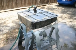 | December 10, 2008 - Before I spend too much time obsessing over the engine, I need to get the car's suspension in place.
That's a fixed location, unlike the engine which has a bit of leeway.
Basically, what I'm going to do is to hollow out the engine bay. The frame rails will come off, along with the inner fenders. That's not a big loss on the passenger's side, it was hammered very hard to clear that massive AC compressor years ago.
Once the bay is empty, I'll rebuild the frame rails with the right geometry to mount my Miata subframe. They're going to look quite different, but they'll attach up to the factory ones under the car if my tape measure is telling the truth.
Before any of this can start, however, I need to empty out the bay a bit more. So I'm pulling all the brake lines, clutch lines, wiring and miscellaneous parts. I've also reinstalled the radiator support to provide a bit more strength to the front of the car during surgery, and welded a couple of posts to it to prevent things from sagging.
entry 103 - tags: suspension, frame rails | | | 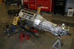 | December 10, 2008 - And here's what is going inside.
I walked into the shop at work and found this behemoth sitting on the floor. I have to say, it's very handy doing this swap at home while there are two LS3 Miatas being built at work as well as a completed LS1 Miata that's undergoing constant development. That's the drivetrain from the LS1 car, removed to get new heads and a cam.
It's a pretty close match to what I'm going to use. The subframe is the tubular version of a Miata subframe, with the same control arms and steering rack. It looks as if my engine positioning will be a bit further back than this one, which helps a bit for rack clearance, oil pan clearance and weight distribution.
It sure makes the transmission look huge!
entry 104 - tags: engine, subframe, transmission, fitment | | | 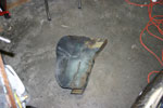 | January 3, 2009 - And out comes part of the engine bay.
We cut the frame rail off at the firewall and again at the factory radiator support. A big chunk of inner fender was removed as well. More will come out later, but this is a good start. And it was dramatic enough to keep Janel happy.
entry 127 - tags: destruction, frame | | | 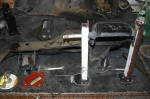 | January 9, 2009 - Time to build the brackets for the upper control arm.
Step one, get my hands on a front subframe that doesn't have the rear mounts hacked off. Oops! Luckily, there was one in the metal dumpster at Flyin' Miata.
Step two, build a jig to locate the upper control arm mounting points in space. This isn't exactly a production quality jig, but it'll do for a one-off. It's accurate, which I tested by removing and replacing the stock piece a few times. A couple more pieces were added after this picture was taken, but you get the idea.
entry 131 - tags: suspension, frame, jig | | | 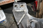 | January 9, 2009 - The upper arm is bolted onto this tube.
It's a metric size, and there's nothing quite right available off the rack. I don't want any slop in the long bolt that runs through the tube for obvious reasons.
So I went back to the sacrificial subframe and chopped one out. Here you see the before and after. There's an amazing amount of weld on this tube, there was lots of grinding involved.
entry 132 - tags: subframe, suspension | | | 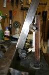 | January 9, 2009 - Here's a rough approximation of how the upper mount will be supported.
A section of the same 2"x3" square tube that makes up the chassis rails will go up and out, and extend beyond the upper arm mounting to provide the upper shock mounting location. Some fore/aft bracing will be added later, and I'll run something from side to side at the top if the engine allows. The base of the bar will also move closer to the center of the frame rail, this is mostly just a convenient place to sit it right now.
I could mount the bar like this, with the upper arm mounting tube welded to the side of the bar. That gives a slightly better location for the shock mount.
Another option would be to angle the bar more and run the tube through the center of the bar. That would be stronger for the tube, but less ideal for the shock mount. Since the shock mount is going to get big loads (the vertical loads from the car go through it while the upper arm mostly has to deal with some side loads and a forward load on braking), I'm thinking the first option might work better.
I'm starting to wonder if I'm going the wrong way here. Should I have the frame rails kick upwards after the firewall, supporting the lower control arm mounting points with a crossmember that dips down under the engine? I'm worried about twisting loads coming from that upper shock mount located so far away from the rail. I could tie into the body, but there's not really much there. Then again, the Miata doesn't have a whole lot of metal in that area and there are no side loads on the shock due to the double wishbone configuration. Meanwhile, the lower control arms take the brunt of the cornering loads from what I understand. Hmm.
entry 133 - tags: suspension, frame | | | January 9, 2009 - While looking around to examine various frame designs, I came across this ambitious project.
A Miata stuffed inside an Morris Minor. I've seen it in the past but had forgotten about it. And check it out, there's the same suspension setup I'm working on. No pictures of the final product which is a shame, but there are some good ideas in there. I like the wood mockup.
entry 134 - tags: suspension, frame | | | January 10, 2009 - Okay, I think I have it.
The crossmember to mount the steering rack actually has to go directly in line with the front lower control arm mounts. I can use a plate or some bars to triangulate the upper mount points to this, getting rid of my twisting problem. It's still a ladder frame with the torsion problems that implies, but a full space frame isn't going to happen at the front of this car.
I'm going to keep thinking about this, both how to implement with the lower control arms as-is and how to deal with the upper location, but I think I'm on the right track.
entry 135 - tags: suspension, frame | | | 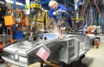 | January 11, 2009 - Ooo, a naked MG!
This is from the very cool British Heritage website. From this and other pictures, I have a better idea of where the various beams and strong points are to be found in the body shell. For example, there's a beam at the top of the fender that I'd never noticed before.
I'm going to triangulate my suspension pickups off them, making a pseudo-spaceframe out of the front end. I have a number of the new tubes figured out, but I won't sort out their final locations until the engine is in place. I suspect a few of them will have to be removable as well to deal with engine serviceability.
One thing that occurred to me yesterday is that the high frame rails with a dropped crossmember for mounting the lower control arms won't work with Miata geometry. The front and rear pickup points are a long way apart, and the crossmember for the rear one would go right through the oil pan. That's not good.
entry 136 - tags: suspension, frame | | | 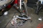 | January 11, 2009 - It doesn't look like much after all that work.
Still, here's the first corner of the new frame. When I look at it in the car, I realize how short many of these distances really are. Most of the length of this bar will be welded to the bottom of the car, both to the floorboard and tied into the existing frame rail. It's not going to be difficult to make everything stiff and solid. I spent most of my working time today finishing some of the design work in my head, and I'm pretty happy with it all. This is just a skeleton.
You can barely see it in the picture, but the upright is welded to the front suspension pickup. I'll add in an extra triangle to help spread the forces around as well as tie into the crossmember that will support the steering rack. The upper end will be tied into the top of the fender and the beam in there, as well as back to the firewall on a bit of an angle. I'm also planning a little more bracing to tie the upper control arm mount to the upright a bit more - nothing complex.
The one mistake I made was that I didn't cap off the end of the upright, and it's going to be tough to do now. I don't really want to leave it open to the elements either. Whoops. It's possible to do, but it will be awkward. Then again, there's no chance of water getting trapped in there now! Is it better to make it watertight (hopefully!) or to make it irrelevant if water gets inside?
entry 137 - tags: suspension, frame | | | 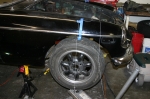 | January 14, 2009 - It's time to put some suspension on the car.
First, I need to identify exactly where the wheel will go. The centerline was marked with the plumb line. Then I took a measurement from here to the crossmember under the car, where my new frame rails will terminate. As do the originals.
entry 139 - tags: suspension, frame | | | 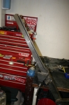 | January 14, 2009 - In order to fit the new frame rail to the bottom of the car, it has to be cut to match the contours of the floorpan.
There are enough little dips and lips to make this a real pain in the butt, actually. Lots of careful measuring and turning parts around in my head, then it was time to cut.
entry 140 - tags: suspension, frame | | | 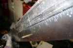 | January 14, 2009 - All that careful measuring, and I cut with a Sawzall.
Actually, it's possible to be pretty accurate with one. Check out how straight that edge is! I can't do that well with a bandsaw.
entry 141 - tags: suspension, frame | | | 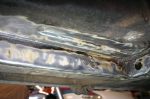 | January 14, 2009 - Before I could attach anything, I had to clean off the frame rails.
That's some good looking metal for a 37-year-old British car! I used a wire wheel on my angle grinder to clean it up. Really, I don't need to clean up the side of the original frame rail as I can't weld to there, only the edge.
entry 142 - tags: suspension, rust, frame | | | 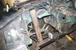 | January 14, 2009 - After innumerable test fits, small tweaks and a wholesale chop of a 3/4" strip down one side, the suspension is ready to weld in.
Note how the upright goes right into the front fender. It lines up nicely with the support behind the fender. So that's good!
You can see the angle level I'm using to make sure everything is correct. After all that test fitting, I still ended up with a surprising gap between the top of the rail and the floorboard. I'll fix that either with a piece of small angle welded in (which will actually provide a little more stiffness, I think) or by persuading the thin floor to move slightly. It's not far off, but it doesn't take much for a weld to be a problem. I'm also probably going to have to see if I can remove the asphalt sound deadening from the floorboards. Now that is going to be a pain.
Everything's just welded enough to hold it in place, although I can't call some of those welds under the car tack welds. They're pretty beefy. The ones at the top of the upright are tacks, though.
entry 143 - tags: suspension, frame | | | 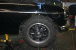 | January 14, 2009 - So, how did the wheel align after all that?
Almost perfectly. It looks like it's moved forward slightly from my ideal, but not enough that anyone will ever notice. The only problem is that according to my angle level, I don't have much negative camber. I think I'll move the top of my upright inboard just slightly, enough to move the adjustment range more into the negative range. Before doing that, though, I'm going to measure it again tomorrow. I should tighten all the suspension bolts more first to make sure I'm getting accurate readings, they're all just finger tight right now.
The suspension has lots of room to move and it's all nicely fixed to the car. Some extra braces will be coming to reinforce the upright, but this is enough to get me started.
Now I just do the same (only faster!) on the other side of the car, then put the crossmembers in. And with that, I can start to figure motor mounts, steering column routing, wheel flares and a bunch of other items. Here we go!
entry 144 - tags: suspension, frame | | | January 20, 2009 - Whoops.
I got the second frame rail cut to shape and tack-welded into place. Then, just to check my placement, I checked the horizontal distance between the front control arm mounting points.
They were about 10mm too wide.
That's odd, how could I have made that miscalculation? Just for fun, I checked the distance between the rails at the front. Again, about 10mm too wide. But the rails were pushed up tight against the inside of the stock rails, so how could that have happened? A bit of head scratching and then I checked the width of the rails at the firewall. Perfect.
They're splayed.
So I crawled back under the car again to see if one wasn't butted tight against the stock rail, but both were good. Sighting along the new rail showed me the problem, though. The rails weren't straight. In my excitement to put the suspension pickups in place, I'd managed to warp them. Obvious in retrospect, not something I expected at the time. At least it appears I did it nice and evenly, but this isn't good.
So I think I'll try heating up the inside edge of the rails and see if they pull back straight. It's a trick I learned from an exhaust shop - heat up the steel and let it cool, and the hot side will shrink down a bit. Basically, do the same thing that bent them in the first place. Either that or I cut them loose and start over, or cut and weld the rails with an angle correction. Ugh. I'll try heat first.
entry 151 - tags: suspension, frame, ok | | | January 21, 2009 - Some more thinking on the frame rails.
I'm going to replace them, and I'll take the opportunity to bump the wall thickness a bit. Just because. The mounts will get cut off the existing rails and welded on. I know how I can do this without needing to go through all the fixturing again.
This is the smart choice. I was trying to think of easier ways, but it'll only be another couple of hours worth of work, and it's the strongest and best solution.
entry 152 - tags: suspension, frame | | | 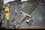 | January 26, 2009 - After a fairly short and noisy period, the frame rails were removed from the car.
I then proceeded to chop them up and remove the brackets. Voila, ready to weld on to the next rails. Slowly, without too much concentrated heat. The only thing I have to worry about is getting the brackets the correct distance apart, and for that I'll simply weld them in with a lower control arm in place.
In other news, I took the Camaro in to work today. Everyone was surprised, as they assumed it had been gutted some time ago. Far from it - they're much more compact when fully assembled! I'll order a coolant temperature sensor tomorrow so I can make sure the temperature problem is sorted out before the engine goes in the new car. And I also noticed the big black car has cruise control. Hmm, how could I integrate that while making it appear completely vintage? That could be a pretty cool addition...
entry 153 - tags: camaro, suspension, frame | | | 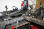 | January 28, 2009 - I picked up some more steel for the frame rails.
This new stuff has a thicker, 11ga wall and is hopefully straight. Step 1 was to weld on the front control arm mounting point, then I bolted up a control arm and used that to fixture the rear. Quick and easy. The relationship between the lower and upper control arms is handled by the fact that the front mounting point remained fixed to the upper one.
entry 154 - tags: suspension, frame | | | 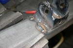 | January 28, 2009 - To minimize the chances of warping, I moved around the pieces to weld them.
The idea was to never let one area get too hot. The thicker wall also helps here.
entry 155 - tags: suspension, frame | | | 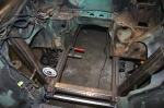 | January 28, 2009 - With the frame rails assembled, I cut them to shape to fit the floorpan, then tacked them into place.
They went in quite satisfactorily and with the angles all looking good. Then, to make sure, I stuck the steering rack crossmember in place after cutting it from a calculated (not measured) length. And it fit perfectly. Everything looks to be centered and the dial level is happy. So we're good! That didn't happen right away, I had to play around with it all for a bit until it all just clicked into place. Sharp eyes will notice that I did have to cut a slot in the frame rails and weld it up, using that to take out a small bit of warp from the welding. It's minor, but spread over a 4' length even half a degree could be problematic. But it's all good now!
I just need to fully weld the frame rails on, then I'll come up with some steering rack mounts. Then, once I know where the steering shaft will run, I can start reinforcing and integrating the new frame into the unibody. I'll also start massaging the transmission tunnel to fit the (huge) T56 transmission.
I feel as if I just unlocked the potential for a large percentage of the project to move ahead.
entry 156 - tags: suspension, frame | | | 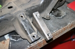 | January 28, 2009 - The next step is the steering rack mounts.
To behind, a fair bit of careful measurement. I want to try to minimize bumpsteer, and the best way to do that is to start with the factory Mazda location and then work from there once the suspension is assembled. I duplicated the factory brackets using a piece of 1x3 rectangular steel. A plate on the bottom will provide some lateral strength.
entry 157 - tags: steering, frame | | | 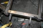 | February 1, 2009 - Time to mount the steering rack, umm, mounts.
I'm still just tacking everything in place, but it's almost time to commit. I did chop a bit of extra frame rail off the sides to clear the rack itself, this was always part of the plan - I figured it was much easier to make them shorter than longer.
entry 159 - tags: steering, frame | | | 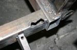 | February 1, 2009 - This cut in the steering crossmember was required to clear the pinion housing on the rack.
It's a bit ugly, these were the chops made to get the clearance I needed.
entry 160 - tags: steering, frame | | | 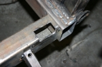 | February 1, 2009 - Once the final clearance was sorted out, I squared off the cut.
Chop chop!
entry 161 - tags: steering, frame | | | 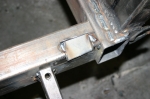 | February 1, 2009 - A small piece of steel was welded in to close up the cut.
It's actually a spare piece of frame rail, the sizing was perfect. Voila, clearance! Once it's welded in completely, I'll clean up the edges with a grinder so it sits flush with the rail.
The steering crossmember could have been smaller, but I wanted the 2x3 tube to give me lots of twisting stiffness for the front of the frame (more than I'd get with a round tube) and to give me a nice flat surface to weld bracing to. Ideally, it should have been 2x2 for packaging purposes so I wouldn't have to do things like this. But that's okay, I think this will end up better overall.
entry 162 - tags: steering, frame | | | 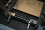 | February 2, 2009 - Remember the steering crossmember that really should have been 2x2?
Well, it's getting closer. To ensure as much oil pan clearance as possible, I had to take a chunk out. Right about an inch at the back and nothing at the front.
entry 168 - tags: steering, frame, clearance | | | 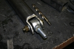 | June 18, 2009 - I spent the day building the mounts for the lower trailing arms.
This is actually going to include a new frame rail, basically, welded to the bottom of the floor and running forward to the crossmember about halfway up. I'm using Dan Master's beautiful GT as a guide here. The new tubes are 2" x 2" with a 1/4" wall. Beefy suckers, but pretty much all the driving force is going to be delivered through these two links.
Let me tell you, if I were doing this for a living, I'd starve to death.
entry 185 - tags: rear axle, frame | | | 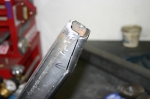 | June 18, 2009 - The crossmember tapers right where the new rail butts up against it, so a bit of pie-cutting, enthusiastic hammering and welding gave me a rail with a matching shape.
Shown here between steps 2 and 3 of course.
Now, when it comes to mounting the rail to the car I'm going to deviate from the Fast Cars setup used on Dan's car. As far as I can tell, they used a c-channel for the rail and stitch-welded it to the floor. The big radius on my tube makes that pretty much impossible, never mind the hassles of welding thin sheet metal to 1/4" steel while lying under the car. So I'm going to drill through the floorboard and use rosette welds. I'll have an easier time getting a good weld and the extra metal in my tube will make the final result stronger. Both ends will be welded up as well, one to the crossmember and the other to the factory spring mounts.
I was about to start doing this when I realized that I should paint the inside of my tube first. It'll be a lot easier now than when it's on the car. I'll put a drain hole in it as well. Not that the 1/4" steel will rust through before the rest of the car collapses into iron oxide from simple humidity, but still...
entry 186 - tags: rear axle, frame | | | June 19, 2009 - I welded the new frame rail to the car last night.
It's not really a frame rail, most like a lower suspension mounting point that's two feet long. But still. 30 or so rosette welds plus a solid connection at each end, I think it should work well enough.
It sure looks weird peeking under the car and not seeing any visible connection between this new rail and the floor. But I know it's there!
entry 188 - tags: frame, rear suspension | | | 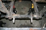 | January 3, 2010 - I pulled the engine out again so I could chase down the fitment problems.
Step one was to reinforce the front end and finish up the welding. Previously, the steering crossmember was only tacked into place and the clearance cuts were unfinished. So I filled them in, added some diagonal braces/fillets and finished the welding. I also closed off the front of the frame rails.
Not visible in the picture is the beginning of the connection between the vertical suspension member and the unibody. The driver's side is partially done. I've also spent some time figuring out the design up the upper shock mounting tabs, as I need to make sure they're in place when I finish the bracing.
entry 246 - tags: frame | | | 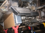 | March 7, 2010 - The structure at the front of the car is now finished.
Not fully welded - that'll happen when the engine is out - but complete. I'm really happy with this. The end result looks pretty obvious, but it took me a while to come up with it as I kept thinking "no, that's too complicated" and taking another look. This is simple, fairly light and should be decently strong. Might make a good sway bar mounting point in the future as well!
I was originally thinking of leaving the ends of the rail open (as can currently be seen on the cross bar) but realized that closing it off wouldn't just look better, it would also add some strength. So I closed 'em.
One detail you can't see on that cross bar is a couple of holes with nuts welded in the backside. Those will be alternate bumper mounting holes, since the originals are now trapped inside the cross bar.
It's quite easy to picture the location of the radiator in this shot, as it's actually in place.
entry 306 - tags: frame, radiator | | | 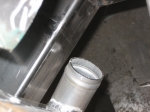 | March 7, 2010 - As usual, everything's tight.
A bit too tight, in fact. When I had the new frame horns and decided to install the rad to show off to Janel what I'd accomplished, I discovered that the radiator outlet was right into the kink in the horn. Argh. So I cut that one off again, chopped 5" off the back end and spliced it into the middle. You can see the ground-down welds in this shot. There still isn't a lot of room for the radiator outlet, but there's enough. That's all I ask.
On the other side of the engine, the alternator has a massive half inch of clearance. Ha, that's miles of room.
Speaking of clearance, I realized that my thought about using pusher fans and moving the rad back wouldn't work. The coolant outlet on the block would get in the way. So nix that idea then. I've decided I'm probably going to use 11" fans instead of the pair of 12" I was trying earlier, as then I can mount them side by side low on the rad. It'll mean most of the airflow will be concentrated on the bottom 2/3 of the core, but since it's a dual-pass setup it'll still hit all the coolant. This gives me more room.
entry 307 - tags: fans, packaging, frame | | | 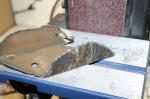 | March 15, 2010 - I dragged the plasma cutter home to chop out the stock frame rails.
It was a very quick and easy job as I'd hoped. I had my welding helmet set too dark so I couldn't see where I was cutting, but it only took a little bit of cleanup afterwards to make everything work well.
Plasma cutters rock.
entry 309 - tags: frame | | | 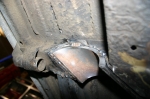 | March 15, 2010 - The frame rail pass-through tacked into place!
Compare the wall thickness of my new pipe to the picture of the removed part. I suspect the car is now stronger. And more importantly, the exhaust construction may now commence.
entry 310 - tags: frame | | | 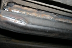 | August 12, 2010 - While I was playing with the welder, I decided to take one more shot at welding the new rear frame rail to the bottom of the car.
Previously, I'd found it almost impossible to weld the two together without burning through the floor. So the rail was attached with rosette welds through the top. But it just looked wrong when you peeked underneath.
With a different technique, I was able to make this happen. I'm much happier with that.
entry 362 - tags: frame rails, suspension | | |
|

 THE DIARY