| LIFE OF A GT |
|
|
 | |  | December 10, 2008 - Turning my attention from the front of the car to the rear, this showed up today.
It's the rear axle from a 2000 Chevy S10 Blazer 4WD. The width is 59", 4" wider than the 2WD rear and a nice match to my front track. I've pulled the brakes to replace them with Miata parts, which is going to involve a bit of bracketry. Still, nothing too exotic. There's also going to be a lot of cutting of old suspension brackets and welding of new, of course.
I wasn't sure if this was going to be a limited slip or not. Experimentation would indicate not, and changing to the Camaro rear will mean setting up the pinion again. Oh well, it's another skill to learn.
entry 105 - tags: suspension, rear axle | | | 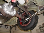 | December 10, 2008 - So, how do I locate the rear axle?
Hanging it off leaf springs just isn't an option for ride, handling and tuning ability. So I'll change over to coilovers and a multi-link setup. Lots of learning here, I've never had to deal with a big stick axle before.
This is a three-link setup as sold by Fast Cars, an MG conversion specialty shop. It would be easier to design and build than a four-link, especially with these photos. However, I'm not too excited about the concept of a panhard rod and the slight lateral movement of the axle it creates - and I'm really not a fan of that bent rod in the Fast Cars kit. This car won't spent a lot of time on the track, but you know it will happen!
More photos of this particular car can be found on BritishV8.org - it's a very thorough conversion and you get a really good look at the suspension design and brackets.
entry 106 - tags: suspension, design, 3-link, rear axle | | | 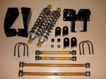 | December 10, 2008 - The other option for the rear is a four-link setup.
It's a little more elegant from an engineering standpoint - the axle is nicely constrained. But it's more of a challenge to design well, as there's potential for binding. I have to admit I'm not completely sure how to design that, or if it's really a risk. I've been running the kinematics of both designs in my head all day, trying to figure it all out.
The picture is of a commercially available kit from Classic Conversions, and it's actually designed to bolt into the chassis. Pretty nice. According to a writeup (with more pictures) on BritishV8.org, it's designed to have a bit of roll oversteer which is something I'd prefer to avoid. Still, it's a good option - although with a price of over $1000, it's more likely that I'll use it as a proof-of-concept.
entry 107 - tags: suspension, rear axle, 4-link | | | December 15, 2008 - Not much actual work on the car, but lots of planning.
I'm going to go with a three-link rear after talking with a number of road racers and other folks on the Grassroots Motorsports forum. The lateral motion of a long Panhard bar isn't a big deal at all it seems, and it's free of bind and easy to fabricate. So there's that settled. I just have to do it!
I'm also starting to plan the brake system. Very little of it will be MG by the time I'm done. In fact, it's possible it will all be custom. I'll have to wait until the motor position is determined before I can finalize this but it's fun to build it in my mind. Brakes are important to me, and I like putting together good systems.
This is actually a very entertaining part of the build. I have all of the major components so I can start legitimately planning and figuring out how to do things. On top of that is the anticipation of the first big steps coming up - I'm looking forward to that first chop of the frame rail with anticipation and a little frisson of nerves. This is the stage where the whole car comes together in concept, making it a complete machine instead of just a collection of bits that are a reaction to unforseen problems.
I love this part.
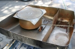
entry 108 - tags: suspension, brakes, rear axle | | | 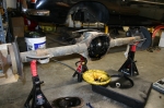 | May 27, 2009 - Finally, some real work!
In a fit of procrastination, I dragged the S10 rear end into the garage to pull the axles out. That'll let me get started on converting them to the 4x100 pattern and also mount the Miata brakes. Then I'll build the 3-link setup.
First step, of course, is to drain the fluid. It actually looked pretty clean.
entry 177 - tags: rear axle | | | 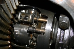 | May 27, 2009 - I was a little surprised when I saw the differential.
Using the classic "turn one wheel and see which way the other one goes" test would indicate this is an open diff. But there's some extra machinery here and what looks suspiciously like a clutch pack. The upper doodad spins when I turn one wheel, and it's spring-loaded and can open up. High rates of spin might lock up the rear or at least bring the clutches into play. At least, that's my theory right now. Interesting little thing though!
entry 178 - tags: rear axle | | | May 29, 2009 - Well, I was right on the function of the differential.
It's a clutch pack that is brought into play with a wheel speed difference of 100 rpm or so, and disengages at over 20 mph. So, might be useful when trying to get out of a mud pit, but not so much for our use. Thus the original plan of using the Camaro differential remains.
entry 179 - tags: rear axle | | | 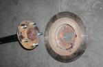 | May 31, 2009 - The next step with the rear end is to figure out how to fit Miata brakes and wheels to it.
There's an obvious problem here - too many studs! The Miata uses a 4x100 bolt pattern. The diameter of this flange and the raised "hub" in the middle also need to be cut down. So I've passed it off to a machinist to make everything fit work. I don't think it's too hard a job with a lathe, but without a lathe it's pretty tough!
It's not really a big step, but having Miata wheels mounted to the rear end with brakes will make me feel like I'm really getting somewhere. Plus Janel approves of the fact that the S10 rear end is no longer in her way near the garage door.
Anyone need an MGB rear end?
entry 180 - tags: rear axle | | | June 4, 2009 - Well, apparently my hope of having the stock axles modified was a bit premature.
The machinist says the center bore can't be brought down all the way to Miata diameter, so my rotors would also have to be machined for a bigger bore or I'd have to use a different rotor - one off a Civic might do the trick, for example, as they have a larger center bore. The estimated cost is around $245 for the work.
Meanwhile, Moser Engineering will make a set of brand new high strength axles for $295. I think I'll go that way.
Of course, if I'm buying new axles, I could simply have done that in the first place and shortened the Camaro housing and saved a bunch of money. I didn't look into the price of custom axles ahead of time. Still, with the S10 housing, I'm assured that everything is straight and aligned which will avoid some potential problems.
entry 181 - tags: rear axle | | | 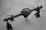 | June 7, 2009 - The rear axle has a few brackets on it that I won't need.
The brake line brackets and the two big spring mounts are going to go. I'd like to reuse the brake mounting tabs at each end if I can, a well-designed adapter should let me simply bolt the Miata parts on. At least, that's my theory.
entry 182 - tags: rear axle | | | 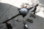 | June 7, 2009 - An hour or so later, the housing has been reworked.
Those spring mounts were extremely solidly welded on, let me tell you. Lots and lots of bead. Still, nothing an angle grinder and a hammer wouldn't fix. I also wire-wheeled the axle tubes to clean them up as I'm going to be welding on them and, well, it's just more pleasant dealing with clean parts. The rear cover was also thrown into the bead blaster to get the worst of the junk off, inside and out. It'll all get painted black, as I'm not really looking to emphasize the differential.
As soon as I can get my axles back and make a couple of measurements, I'll get those new ones ordered. That will let me mount the brake rotors and work on the brake brackets. It'll also let me bolt on wheels so I can start work on positioning the axle and building the three-link rear.
entry 183 - tags: rear axle | | | June 9, 2009 - I was thinking about the best way to proceed on the car, and decided it was time for a few parts.
First, of course, I need to order those axles. But I had to retrieve the stock ones from the shop that had looked at the possibility of turning them down.
So while waiting for that, I figured I'd look at building the brackets under the car. But before I could do that, I had to get my hands on the rod ends I'd be using for the arms on the suspension. Actually, they're not rod ends. They're similar to rod ends with a threaded end on them, but they have bushings in them instead. Better manners for a road car, you see. I should have them before too long, then I can start working on the bracketry on the car.
This order involved a lot of time poking through various fascinating circle track catalogs. It's a very specialized but standardized field, and I have no idea what some of these parts do. It's fun trying to figure it out!
entry 184 - tags: rear axle | | | 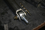 | June 18, 2009 - I spent the day building the mounts for the lower trailing arms.
This is actually going to include a new frame rail, basically, welded to the bottom of the floor and running forward to the crossmember about halfway up. I'm using Dan Master's beautiful GT as a guide here. The new tubes are 2" x 2" with a 1/4" wall. Beefy suckers, but pretty much all the driving force is going to be delivered through these two links.
Let me tell you, if I were doing this for a living, I'd starve to death.
entry 185 - tags: rear axle, frame | | | 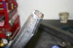 | June 18, 2009 - The crossmember tapers right where the new rail butts up against it, so a bit of pie-cutting, enthusiastic hammering and welding gave me a rail with a matching shape.
Shown here between steps 2 and 3 of course.
Now, when it comes to mounting the rail to the car I'm going to deviate from the Fast Cars setup used on Dan's car. As far as I can tell, they used a c-channel for the rail and stitch-welded it to the floor. The big radius on my tube makes that pretty much impossible, never mind the hassles of welding thin sheet metal to 1/4" steel while lying under the car. So I'm going to drill through the floorboard and use rosette welds. I'll have an easier time getting a good weld and the extra metal in my tube will make the final result stronger. Both ends will be welded up as well, one to the crossmember and the other to the factory spring mounts.
I was about to start doing this when I realized that I should paint the inside of my tube first. It'll be a lot easier now than when it's on the car. I'll put a drain hole in it as well. Not that the 1/4" steel will rust through before the rest of the car collapses into iron oxide from simple humidity, but still...
entry 186 - tags: rear axle, frame | | | June 18, 2009 - I ordered the custom axles today.
It took a fair bit of back-and-forth with Moser to determine that my cunning plan of narrowing the axle by making the radius on the back of the flange thinner wasn't going to work. So they'll be the standard width instead of the slightly narrower setup I'd hoped for. Oh well, there's a 1/2" of tire clearance gone. The good thing is that the standard length axles are $245 instead of $295. They'll be here in a week!
entry 187 - tags: rear axle | | | June 25, 2009 - I just realized that I goofed.
I picked up some nice 4-bar ends from Speedway Motors a while back to serve as the ends of the various suspension arms. I prefer these for a street car because they'll be quieter than the more typical rod ends. Hopefully I can get replacement bushings for them! Anyhow, I ordered 6 without realizing that there's a left-hand thread version. The latter is pretty hard to find on the Speedway website and I only stumbled across it after some pretty determined digging.
And of course, the pretty swaged steel tubes I was going to use for my chassis arms come with a right/left thread. So I've ordered 4 of the left hand ones now - I've decided to use a pair on the Panhard rod as well as the trailing arms. I'll have two right hand pieces left over when I'm done, but such is life.
Meanwhile, parts are coming in. A set of ARP studs for the new axles arrived today (Camaro ones that cost $12.00 for a set of five, it's not worth buying stock Miata ones for that!) and the axles themselves should be here tomorrow. Once I have them, I'll mount up some wheels and figure out the exact axle location.
Meanwhile, I've been under the car and realized I'm going to have to do some more cutting around the rear bulkhead to make room for my center link. No worries, it just means more time under the car getting showered in metal shavings. The second pickup point is also welded into place now.
entry 189 - tags: rear axle, suspension | | | 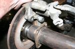 | June 28, 2009 - The new axles have arrived.
Now I can mount the Miata brake rotors and wheels to the S10 rear housing and that opens up a lot of potential work. The picture shows what needs to be done to fit the brakes to the housing - I'll weld a new bracket on to the tube. I'm not sure if I'll try to cut the original one off or not, it'll be a huge amount of work if I do. Depends on the access I have for welding the new one.
I have one wheel mounted on the rear now, I'll install another one soon and roll the whole thing under the car to see how they sit. I already have a pretty good idea, but of course I'm still eager to see it.
entry 190 - tags: rear axle, brakes | | | 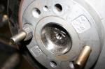 | June 28, 2009 - The picture shows just how tight the tolerances are - check out the fit of that center hub in the brake rotor.
It's absolutely perfect. I have to admit to a certain amount of nervousness the first time I slid the brake rotor over top, but my measurements and Moser's fabrication are just right. The rotors fit as if this was their factory application.
The best part is that, because I didn't change the axle length, it was only $245 to get the new parts made. "Only" because that's a pretty killer price for a pair of high-strength custom axles - far less than the quoted cost to rework the stock ones.
It's hard to explain why I'm so excited to see rotors and wheels on the rear end, but I am.
entry 191 - tags: rear axle | | | June 30, 2009 - Oops.
I decided to install the axles in the differential last night. Imagine my surprise when it became obvious they just weren't going to fit. The inner end of the axles was about 0.035" too long, preventing me from assembling everything. That's a bit frustrating.
An email to Moser and the current theory is that my axles were made with a "button" intended for an 8.5" differential. Mine's a 7.625" setup. So they're going to make another set and I'll return these. Good thing I didn't press all the studs into the flange yet!
entry 192 - tags: rear axle | | | July 25, 2009 - Janel and I took a bit of a break and headed off on a trip for a while.
Three weeks away is great for clearing the head. Plus, it meant that there were a new set of Moser axles waiting for me upon my return.
But I have a problem. Part of the error in the original Moser axles was a C clip groove that was 0.025" too large in diameter. So I had to tap the clips into place. If I had more experience with these sorts of axles, that should have been a danger sign. The result is that I simply can't get the clip off one of the axles. It's the side with the ring gear, which is blocking my access somewhat.
I've been fighting this for a while. Right now, it looks as if the best option will be destructive removal of the clip, and the best suggestion I've heard for that is freezing with liquid nitrogen and then employing a short, sharp shock with a chisel. Cutting doesn't look plausible due to access problems. I'll cut the axle in half if I have to, but I have to figure out how to get in there to do the cutting.
The good news is that the only part of this whole assembly I really need to keep is the housing. If I have to cut the differential apart, so be it.
I also learned yesterday that Z28 Camaros have a Torsen differential. Excellent. No, wait, that's 1999-02 Z28s. Our donor is a 1998. I think that means we have a Positraction. I'm trying to learn more about that now.
entry 193 - tags: rear axle | | | July 26, 2009 - I win!
I always win. It's just a matter of how much the car has to suffer, really.
I asked the creative minds on the Grassroots Motorsports forum for suggestions. While I initially homed in on the liquid nitrogen option, one comment stuck with me. Drill a hole for a screw and pull it out. But if I can drill a hole for a screw, what if I drill a larger hole and cut the C clip in half?
I didn't quite manage to break it in half, but I weakened it enough that I was able to spread the clip apart and remove it. Voila, the axle has gained its freedom!
Unfortunately, that's liable to be the end of any work on the MG for some time. I'm working on a new book and it's late. Very late. My editor has run out of smiles, so all my free time for the next few months will be spent putting words together. The MG will resume once I have also gained my freedom.
entry 194 - tags: rear axle | | | 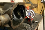 | November 12, 2009 - Time to weld the brackets for the lower arms to the axle housing.
Of course, the housing is round and there are many ways I could stick the parts on them crooked. The back of the differential housing is perpendicular to the pinion, so I set that up to be vertical. A Miata jack under the nose of the housing let me finely adjust the angle. The arms were also set up to be level.
After all that welding in and under the car, having the pieces sitting in front of me on my solid workbench is a real luxury!
entry 206 - tags: suspension, rear axle | | | 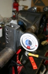 | November 12, 2009 - With the housing properly located, I did a bit of final fitting.
The brackets need to be 905mm apart on the inside edge and vertical in two planes. A bit of careful work, some solid tack welds and voila!
Except I made a mistake. The brackets on the chassis aren't designed to use washers. These are, and I forgot to take the thickness of the washers into account. They're right around 3/32" thick, so I have the brackets 3/16" too far apart. Argh. Is that enough to be a problem? Will I have to cut the brackets off and move them? I don't know. I'll get the tubes and test fit, and see if there's any sign of binding. I have a couple of ideas that don't involve the grinder, but that really would be the smart solution.
entry 207 - tags: suspension, rear axle | | | 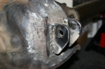 | November 17, 2009 - Thanks to Brandon, the brackets are welded on the top of the diff.
I ran the torch, heating the whole area up to about 700F. Once the heat had stabilized, Brandon stick-welded the brackets on with a nickel rod as I continued to play the torch around and keep things warm. Once the welding was done, I continued to heat the differential and gradually brought the heat down. Once we got it down to about 450F, we wrapped the whole thing in a welding blanket and let it cool gradually overnight. The end result? No cracks!
Brandon would probably like me to mention that it's a bit out of practice, but the welds are strong. I tested them by beating on them with a hammer.
entry 208 - tags: rear axle | | | 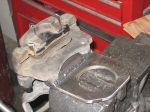 | November 19, 2009 - The brake brackets are ready to weld on to the axle tube.
I'd been trying to figure out the best way to ensure the holes were in juuust the right place. I needed to get the radial location of the caliper just right. Measuring wasn't going to work well as I was dealing with curved surfaces everywhere. After a bit of cogitating, I came up with a cunning plan. Naturally, I wasn't bright enough to take pictures of the process, so I'll have to try to explain.
First, I used a transfer punch to mark the center of the two holes in a piece of 1"x0.25" strap. This is my 0.25" spacer. I drilled those out (I found a step drill that was close enough to 10mm to solve my previous problems) and checked that they were accurate on the caliper.
I then took a couple of bolts and cut them down into short studs, which protruded out of the caliper by 0.25". This way I could hang the spacer on them and butt it up flush against the face of the large bracket piece.
Now the axle and brake rotor were mounted to the rear end. I placed the caliper in the perfect location and held it in place by tightening down the adjuster screw Mazda thoughtfully provided, clamping the caliper in the right spot. Now it was a matter of assembling all of my pieces - the bracket on the axle (loose) and the spacer hung on the caliper. I lined everything up and tack-welded the spacer to the bracket. Now, I had my holes lined up! I drilled the rest of the bracket to match, welded it up and voila.
The second was easier. Now that I had one accurate bracket, I used the transfer punch (wonderful things, these are) to put the holes in the same place and stuck it all together.
Now all I have to do is figure out just how I want to clock the calipers on the axle. I'll mount the rear end to the car and find out if there are any potential interference points with the body.
entry 212 - tags: brakes, rear axle | | | 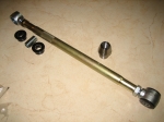 | November 19, 2009 - A big box full of MG suspension parts arrived in the mail!
Well, I know they're MG suspension parts. Most people probably wouldn't identify them as such.
A collection of swedged rods for my trailing arms along with 4 left-hand thread ends. I'm sure I ordered the latter back in the summer, but they're nowhere to be found. At worst, I have some spares.
I also picked up a couple of weld-in bungs so I can build the Panhard bar. I'm pretty close to that point. Cool.
entry 213 - tags: rear axle, suspension | | | 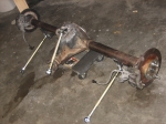 | November 20, 2009 - Time to assemble the rear and attach it to the car!
First off, with the differential, axles, brakes and trailing arms attached, it's really heavy. Yowza. Lifting this thing off the workbench was an excellent illustration of unsprung weight.
entry 214 - tags: rear axle | | | 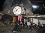 | November 20, 2009 - The axle in its new home!
It took a bit of fiddling around with trailing arm length to get it in just the right place, and I think I'm going to have to pick up some lower ones that are an inch longer. No worries, they're only about $12 each. I'm actually really liking these, I'm trying to think of other cool places to use them. It's super-easy to adjust the pinion angle and the rear axle angle.
In this picture, I have the jackstands at different heights - the arms are usually parallel! I also took the shot before I went on a major garage cleaning binge. That's how it usually works, right?
entry 215 - tags: rear axle, suspension | | | 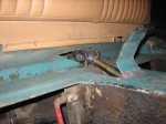 | November 21, 2009 - With the axle actually attached to the car, I was able to move it through the full range of motion.
As I suspected, at full compression the upper link hit the bottom of the car. After a bit of fine metalwork, I had that problem solved! Right now, maximum compression is actually a bit more than was available on the original suspension. My tires are a smaller overall diameter but since they're further outboard, getting this much travel is going to involve quite a bit of surgery to the wheel wells before the fender flares go on. The plan to to build the car to allow this much travel, then use spacers to limit it to less if that should become necessary for any reason.
It was very cool to be able to put the axle through its paces and see how things worked, then simply reach up and tweak the pinion angle or the fore-aft location.
entry 216 - tags: rear axle, suspension, travel | | | 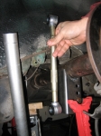 | November 21, 2009 - I'm still playing around with places to put the coilovers.
This rod is the same length as a fully compressed AFCO shock with 5" of travel. With the suspension at full compression, it helps me determine my worst-case scenario for mounting points. I'm starting to lean towards putting the shock in the wheel well. It'll take up a bit of space that could be used for tire, but on this axle there aren't really any options for moving the tire inboard much anyhow. As long as I have an inch or two of clearance, it shouldn't cause any real problems.
If I do decide to narrow the rear axle to allow more tire - since this is a street car, not a drag or track car, I don't need monster rubber - I can always move the shock. The good thing about this setup is that I'll have more ground clearance and I'll have a much easier time welding in a strong upper mount for the shock than if I tried to use the mount for the travel limiting strap.
entry 217 - tags: suspension, rear axle | | | November 30, 2009 - The weekend wasn't completely without progress.
I got all itchy to do something productive so I figured out how to mount the Panhard bar and also welded the brake brackets on to the axle. One step closer. I'll do the messy fabrication work for the bar this week and get it all put together.
I also took advantage of a Black Friday sale at Discount Tire Direct and picked up some new tires for the car. The eventual plan will probably involve some 15x8 wheels in the rear with 225/45-15 tires, but I'll probably have to shorten the rear axle to do that. For the initial build, I'll stick with my current setup of 14" wheels with 195/60-14 tires. Yes, miniscule by modern standards and the skinniest tires on any vehicle I own when I think about it. But I have the wheels, they look appropriate on the car and I have the wheels. The tires are a set of Falken Azenis RT-615s, and I got the full set for $176 delivered. Can't beat that for value. They might be small, but they're pretty sticky for a street tire.
I also just ordered the shocks. Things are moving along. I'm thinking the Christmas holiday will involve the dissection of a certain Camaro.
entry 219 - tags: rear axle, suspension, tires | | | 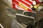 | December 1, 2009 - Panhard rod mount!
As I've mentioned, I'm using the Fast Cars suspension as a base for my design - albeit with a bit more adjustability built in. In that case, the Panhard bar mount is in front of the axle. This means it has to be fairly tall, and it has some support braces to keep it from flexing under side loads. The roll center of the rear axle is the center of the Panhard bar, and the usual geometry means the bar should be in line with the center of the axle at ride height. Thus the long bracket design.
I've decided to put mine behind the axle. This lets me use a straight bar instead of having a bend to clear the nose of the differential. It also means I can take advantage of the contours of the body and use a much shorter mount. It's also a bit of an odd shape and will have a very solid connection to the body of the car. It's made of 2x3 tube instead of the 2x2 in the Fast Car setup and the extra width is in the right place to resist lateral loads. It should be significantly stronger but there's not much clearance for the bar. I think I'll be able to pull it off though.
I should have this welded in to place shortly, I just have to pull out a bit of carpeting inside the car so nothing catches on fire. You know, the usual.
While underneath working this out, I think I figured out how to mount a sway bar to the rear. Hmm.
entry 220 - tags: rear axle, panhard, suspension | | | 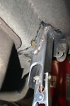 | December 2, 2009 - The Panhard bar mount welded in place.
This is one solid sucker, I'm very happy about that. The bend in the body makes it good and strong.
entry 221 - tags: panhard, rear axle, suspension | | | 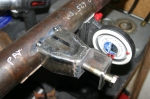 | December 2, 2009 - With the body mount in place, it's time to build the one on the axle.
I welded one of the threaded bungs into a length of 1" pipe and attached it to the body. Then the axle got put into place and I measured the distance from the bar to the axle. That gave me what I needed to figure out what the mount on the axle should look like.
I went through a number of possible designs for this. The final one - shown - has a bracket made of a section of 2x2 bar with a nice thick wall. It's welded to a support made of 2x3 bar, reshaped to meet up. There's a nut welded on the back side of the bracket. A lot of designs I see in circle track catalogs put the bolt in single shear instead of double like this, but I prefer this design.
entry 222 - tags: rear axle, panhard, suspension | | | 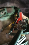 | December 2, 2009 - And voila!
The rear suspension linkages are all in place. The axle is sitting quite a bit lower than usual to show off the bar. In case you're wondering what a Panhard bar does, it provides the lateral support for the axle.
The two outer (lower) trailing arms keep the axle straight in the frame and transfer the brunt of the power to the chassis. The center link at the top of the diff keeps the whole thing from rotating under power and lets me set the pinion angle. And the Panhard bar transfers the side loads into the frame. With this whole lot in place, the axle can twist up and down to let the wheels follow the road, but it will always stay properly aligned to the chassis. Cool.
It's not completely finished, of course. I tucked that Panhard bar into a pretty tight spot, and it only clears the back of the axle by a millimeter or so. More importantly, the bracket on the axle hits the body of the car. A bit of reshaping will solve that problem, of course, but I think I'll have to pull the fuel tank to do it properly. No worries, that looks like a pretty straightforward job.
entry 223 - tags: panhard, suspension, rear axle | | | 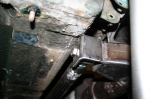 | December 2, 2009 - Here's the interference between the body and the Panhard bar mount.
It's not dramatic, there's only about an inch of up travel left anyhow. It'll be simple to add the space I need without any real consequences anywhere else.
At the top of the picture is the bracket that originally held the straps for travel limitation. I'm thinking it'll be a good place to put a sway bar end link.
entry 225 - tags: rear axle, suspension, panhard | | | 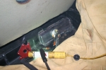 | December 10, 2009 - After filling the garage with smoke and setting the car on fire a couple of times, the body is reshaped to clear the Panhard bar mount.
The welding's a bit ugly as I had a bit of trouble getting a wire wheel in to clear up the floor properly, but it's not terribly structural so that's not important. I'll clean it all up with seam sealer before it gets repainted anyhow.
I'm not sure what to repaint with. There's some sort of goo or tar in there that isn't factory and likes to make a mess of my clothes - you can see some overspray on the bottom of the panel just above my new patch as well as the variation in color. This part of the trunk is hidden beneath the trunk floor and is just used for spare tire storage. It's big, though, and I'd love to put it to work for me somehow.
entry 226 - tags: trunk, rear axle | | | 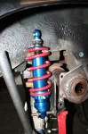 | December 16, 2009 - After a bit of cogitating, I built this lower shock mount for the rear axle.
I'm not completely happy with it, it's not as elegant as I'd like. But it should be strong enough. It's 1/4" plate, welded to the lower trailing arm bracket as well as to the axle tube. There's a triangular reinforcement taking care of some fore-aft strength. I'm still redesigning it in my head, we'll see. That lower shock mounting point carries the entire load of the car (well, 1/4 of it). Assuming the car is around 2600 lbs and evenly balanced (possibly both fairly big assumptions), that means there's 650 lbs on that perch. If it's designed for a 3g load, that means it has to support approximately 2000 lbs. I'll definitely be monitoring this!
The upper mounts will be attached to a plate that will spread the load somewhat. At least, that's my plan. We'll see how that works out.
Underneath the bumpstop, you'll see part of the original MG axle sitting on top of my axle tube. This means I'll have the same bump travel as the original suspension. I'm estimating a bit here, trying to set the shock up so it doesn't quite bottom out at full compression. I expect to have to do some fine-tuning in this area.
entry 228 - tags: rear axle, suspension | | | 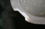 | February 20, 2010 - I did have to make one small alteration to the fuel tank.
This corner bumped up against my Panhard bar mount and kept me from getting the tank quite snuggled into position. A moment with the grinder solved that problem. You can see that the stock tank is actually crimped together. I was careful to stay clear of that section.
While I was goofing around underneath the car, I also removed the rear axle and relocated the lower shock mounting points an inch higher. This will give me a better bump/droop ratio for the suspension travel.
entry 294 - tags: axle, fuel tank | | | 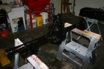 | June 19, 2010 - The rear axle, fuel tank and panhard bar have all been given a coat of POR-15.
So has the pedal box. I also hit some of the brackets welded on the car to use up some of the leftover paint. Once the tank is dry, I can do the final installation and not have to take it out again. Woohoo!
entry 350 - tags: paint, fuel, axle | | | 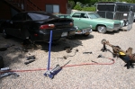 | July 17, 2010 - Okay, there's that done.
The black bumper was painted, then sanded down again and painted again. I learned a huge amount about sanding on compound curves, surface prep, paint gun setup and the general unforgiveness of shiny black paint. But now I'm in pretty good shape to paint the MG. Not that I'll remember any of this when it comes time to paint! I also made a trip back to Canada for a week or so.
But now it's time to get cracking. I have to drop a differential off at the drivetrain shop for work, so I figured I'd bring the Camaro and MG axles in for their diff swap at the same time. I don't know how to set up a rear end and I'm happy to let someone else do it for me. So I jacked up the Camaro and had at it with the tools. An hour later, the rear end was free in the driveway.
Note the very large boards underneath the jackstands, this car is not going to sink into the gravel, fall off the stands and kill me.
entry 353 - tags: Camaro, differential, rear axle, paint | | | 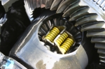 | July 17, 2010 - Here's a peek at the differential from the Camaro.
In 1998, the Z28 came with a Positraction differential. In 1999, that was changed to a Torsen. This is a Posi, although I do have to admit to resorting to Google to make sure I wasn't looking at some sort of Phantom Grip nastiness.
Miatas used Torsens from 1994, and it's a great differential. Very easy to drive. But the V8 cars we've been building at Flyin' Miata have been using a differential from a Cadillac CTS-V, and I've been very impressed with their ability to lay down power. The theoretical increase in turn-in understeer hasn't been a problem. I'm pretty sure it's a very similar Positraction to this one. So I'm happy that my donor came with this unit.
entry 354 - tags: differential, rear axle | | | August 4, 2010 - More welding.
It's hot and dirty work doing the fabrication and welding in the engine bay and under the car, but I'm gradually getting through it. The engine bay is almost completely paneled now, but I still have to do some finishing. Then it's underneath to finish up some frame rail work.
I did pick up the rear axle from the driveline shop today, though. All new bearings, all set up with the Positraction rear. All I need to do is stick the axles in, mount the brakes and voila, that's done. It wasn't a cheap visit to the driveline shop, but at least I know everything's done right and I shouldn't have to do anything to it for a long, long time.
entry 359 - tags: axle, differential, fabrication | | | 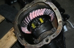 | August 24, 2010 - The differential in its final home.
Quite colorful! Hopefully, this will be the last glimpse of it I see for a while, it's time to button this thing up.
entry 368 - tags: axle | | | 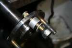 | August 24, 2010 - Before I can install the axles for the final time, it's time to put the studs in.
I tried to overthink this and attempted to press them in with my big bench vice. Whoops - one broken vice. I couldn't get the geometry right to press them in with the press at work. So I figured I'd try what I considered the last resort and use a lug nut to pull them in. That spacer has a nice thick wall so it's strong, and the washer lets the lug spin against it.
And whaddya know, it was quick and easy. I hit the lug nut with the impact and the stud just sucked into place in a couple of seconds. Why did I try so hard?
entry 369 - tags: axles, stud | | | 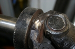 | August 24, 2010 - I found my driveshaft wouldn't give me the ability to get full droop out of my suspension.
That's not good! The problem was two little bosses on the yoke at the transmission end. A couple of minutes with the die grinder and now I have a full range of motion all the way around. The bosses weren't structural as far as I can tell.
One step further! I did a bit more painting with POR-15 under the car tonight and did the final connections on the gas tank, so it's almost time to stuff that axle under the car and call it done. Well, I know it'll come out again for various reasons. But maybe not for a long time.
entry 370 - tags: axle, driveshaft | | | 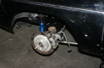 | August 29, 2010 - As promised (threatened?
), the rear axle has been installed. It's full of fluid, has the axles installed, brakes bolted up - it's all looking quite serious now! I still have a few things to do back here, such as working out how to make the Miata and the MG emergency brake systems and locate the platform for the bumpstop. You can see it here sitting on top of the axle. The bumpstop is installed on the chassis. I have to set things up so the bumpstop reaches full compression right before the shock bottoms out. Thus the lack of a spring, so I can do range of motion testing.
I pulled one of the bumpstops off a while back to play with it, and haven't been able to get it back on since. They fit over a mushroom shaped stud, so they have to deform to pop into place. Well, I finally got a brainstorm - I sprayed a bit of Simple Green on the bumpstop (great for lubricating exhaust hangers as well), held it in place, then used a jack to push the axle up. The axle pressed the stop into place with an easy little pop. Sometimes the thinking is much harder than the doing!
entry 371 - tags: bumpstop, rear axle, brakes | | | 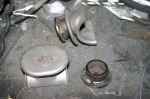 | November 1, 2010 - I didn't feel much like working on the car tonight, but I figured I'd wander into the shop and just do one thing.
Like bolt up that lower control arm that was next on the list before I had to stop yesterday. Arm bolted up, mission accomplished. Then I decided to trace out the cut line for that fender. And then I decided to pop the stainless steel trim off the side of the car to get an idea of how hard it would be (answer: easy). Then I saw the bumpstop targets on the workbench and decided to work on them for a bit.
This is how stuff gets done. By accident!
The bumpstop "targets" are the flat plates on the rear axle that the bumpstop bangs into. I took them off the MG axle. I'm sure they have a better name. Anyhow, I know I need to raise them up a bit for the new suspension. The AFCO shocks can damage their seals if they're allowed to bottom out, so I need to make sure I get this right. But unfortunately I can't tell exactly how much those bumpstops will compress. So the solution is to make them adjustable.
First, I welded a nut to the bottom, underneath the hole that MG thoughtfully left here for this purpose. This gives me the ability to bolt on spacers of various thicknesses. I'm going to start with a 1" pedestal. That's a bit conservative, but I can use a travel indicator to tell how close I'm getting to full shock compression and adjust from there.
entry 419 - tags: suspension, rear axle | | | 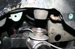 | November 1, 2010 - Here's an image of how the bumpstop target sits on the axle.
The middle of the bumpstop is nicely hollow to allow for the bolt head to fit inside. Notice how clean the 39-year-old bumpstop target is? The bead blaster strikes again!
entry 420 - tags: rear axle, suspension | | | 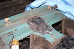 | November 15, 2010 - The top of the diff disagrees with the bottom of the car at full suspension compression.
It's due to the extra bracket on top. So I made a little house for it. I haven't checked to see how the rear seat will sit on top of this, some further creativity may be required.
entry 452 - tags: clearance, rear axle | | |
|

 THE DIARY
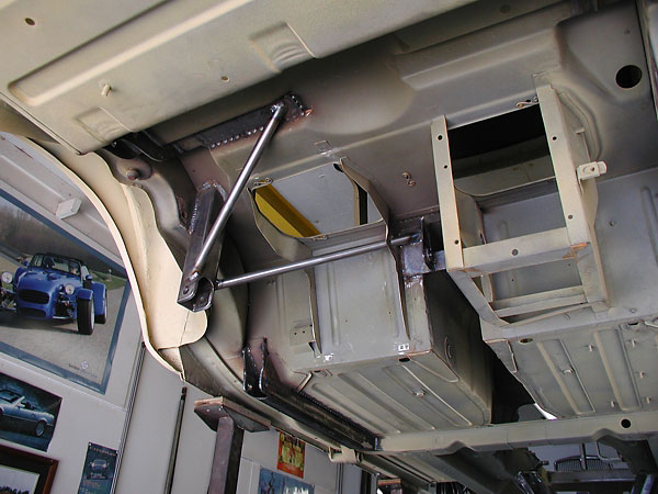